

MXR Flanger Clone
 Over the past few months I’ve been spending a bit of time trying to create a replica of the original vintage MXR Flanger that unlike the reissue, featured an analogue SAD 1024 Bucket Brigade Delay chip. Most people who have tried both the original version and the reissue allege that the first version sounded better, hence why I’ve gone to so much trouble to try and replicate it instead of buying a new version. Besides, the new MXR Flangers are actually quite expensive here, the pricey sum of £125 and over which is much more than a scratch built vintage replica would cost. Some people are deterred from building a clone of this effects pedal due to the scarcity and thus relatively high cost of buying the SAD 1024 BBD chip, however, they can still be purchased online from Small Bear Electronics or Banzai Electronics.
In my searches around the internet I’ve managed to track down quite a lot of various pictures, diagrams, schematics and information for the MXR Flanger. In addition to the schematic by Stellan that’s commonly seen on the internet, I also found the original factory schematic and layout diagram from MXR. Instead of the 120v to 15v mains supply circuit for the original MXR Flanger, I decided that it would be much more practical to incorporate a 9v to 17v step up circuit coupled with a low dropout 15v voltage regulator. This meant that I could either use the typical 9v batteries used with effects pedals, or my preferred choice, the 240v to 9v UK power adaptor that has an adaptor enabling up to 5 pedals to be run from the same mains transformer.
 Vintage MXR Flanger PCB layout by Massimo Ceresa, which he drew up after we sent each other a few emails regarding the MXR Flanger schematics available. This is not the same layout as the original MXR, it’s a bit smaller, but the parts and circuit used are exactly the same so it should sound exactly the same as the original. Click the thumbnail to enlarge the image.
 Here’s the component layout diagram for the above MXR Flanger PCB layout to show you where to put the parts. Click the
thumbnail to enlarge the image.

Extensive parts list, including optional substitutes needed where original parts are unavailable or hard to find. Substitutes should not change the tone or operation of the Flanger in any way. Click the thumbnail to enlarge the image.

MXR M-117 Flanger factory schematic. Click the thumbnail to enlarge the image.

MXR M-117 Flanger factory layout diagram. Click the thumbnail to enlarge the image.
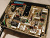
Vintage MXR Flanger photograph courtesy of modezero.com. Click the thumbnail to enlarge the image.

Vintage MXR Flanger photograph showing the rear of the original MXR Flanger’s printed circuit board, courtesy of Massimo Ceresa. Click the thumbnail to enlarge the image.
Coming soon: photographs of vintage MXR Flangers, schematic for 9v > 15v external power supply and more!


The schematic in this page works with 9 or 15V? and where I connect the In and Out in the PCB?
15v. In and out connect to the tip of the jacks you use.
No, I mean Where is located the In and Out in the PCB layout. Are there the C20 sides free holes?
in and out are clearly located in the second image (http://i82.photobucket.com/albums/j279/bainzy007/MxrFlangercomponentsboard.jpg), there’s writing with lines pointing to the PCB hole.
I haven’t checked but I think the sides of C20 are probably + and – for the 15v supply.
Dude, you are right. the correct question was Are the C20 side holes the ground and 15v+ connections?
the 15v’s negative connection goes to ground so yes, they would be ground and 15v+ connections. you should be able to trace which is which by following a ground connection from any component on the diagram. looking at it quickly now though, my guess is that the ground is the hole to the RIGHT of C20, and the 15v+ is to the LEFT of C20.
Last question, the Voltage that is needed to work the MXR is 15V, and what about the Amperage, 500mA or 1000mA do I use?
I’d be very surprised if it draws more than 500mA
The brand new current MXR M117R Flanger pedal draws under 40mA. It varies between 32 to 36mA as the LFO cycles. Check this website for some SAD1024’s for your project. I do have an Electronics Degree but I don’t work for them. I just did a search as I was curious to see availablilty. Although I like my “reissue” and was looking for some possible mods to sweeten it up a bit when I found this page. I was thinking about a mod to slightly increase the fixed delay to bring it into slightly more of a chorusy type of sound.
oh one more thing, if you are doing the 9-17 circuit you might want to use the MAXIM MAX1044 as it has a higher frequecny clock option which puts the oscillator above the audio frequency spectrum.
hey can i get a parts list? i want to build this from scratch for my electrical engineering project and i dont want to have to count the resistors and other components from the pictures
thanks
is it battery operated only?
and on the guitar jack input and output I thought there are at least to wires involved
on each?
It appears that R42 and R44-R47 are missing from the bill of materials. What are the values for these? Thanks!
Please disregard my previous post. I see now that the part numbers on the BOM correspond to those on the factory schematic- I can get the values from there. Thanks, anyway! Great job on this, BTW.
Is it possible to power this circuit with a 18 vdc regulated power supply, then add a voltage divider circuit dropping the voltage to 15 vdc? ( The 18 vdc would stay at the divider ) This seems logical to me since many circuits are powered by 9 vdc dropped to 4.5 vdc utilizing a voltage divider. Any input would be appreciated.
Thanks,
Larry
That’s what I’m doing- 24v adapter to an LM317 regulator. In reference to above post, I tried using the MAX1044 voltage doubler, but the current output was way too low to power the board (I think MAX1044 only puts out about 10mA in that config). Even using an LT1054 (which has a higher current output- 50mA in a voltage doubler config), you might not get enough current.
Would anyone who’s built this be willing to either post or email me voltages at the ICs and transistors? I’m not getting any sound when the effect is switched in. I know that V+, Vbias and gnd are all going to the right place, and that the SAD1024 is good, but could use the other voltages for debugging. Thanks!
I just built this circuit and I think there are some errors that need to be pointed out:
1) The Speed pot is wired wrong on the layout. If you compare to the factory schematic, the wires need to be swapped between the two lugs of the Speed pot. Also, the unused lug needs to be tied to the center lug. THIS ERROR HAS BEEN VERIFIED.
2) The BC549C transistors are shown reversed in the layout. According to the Fairchild BC549C datasheet, they are reversed in the layout above. If you use Fairchild transistors, Q2 should have the flat side facing to the RIGHT and Q3/Q4 should have the flat side facing to the LEFT. I built this circuit according to the TRANSISTOR layout and IT DOES WORK but I do believe that the transistors are oriented wrong in the layout for FAIRCHILD BC549C transistors.
Thanks Greg, wish I had time to update this page with things like parts lists (Alex!) and corrections, but unfortunately right now I don’t, so it’s great that the comments are being used for dissecting it all and can be viewed by everyone.